There are four main components that are assembled together to make a Fresnel lens. A metal frame fashioned of bronze, a set of prisms, wooden wedges, and litharge. The size of the frame varied, depending on the size or “order” of the lens. Bronze was used because at the time, it was the only metal that would resist corrosion and maintain its strength and shape in the humidity and salty air that surrounded coastal lighthouses. The individual prisms were set in the framework and then temporarily restrained while the frames were being assembled. The frame would be assembled in hand numbered sections so that when it was received at a particular light station, it could be quickly assembled. After all the individual frame panels were set together, they were held in place by the base unit at the bottom and by a bronze "collar" at the top of the framework, stabilizing the frame. Once the framework was assembled, the individual prisms were then focused using the wooden wedges. Once focused, the prisms were secured using the litharge. Litharge is a type of lead-based putty that was used to "seat" the glass prisms into the brass frame, and it provided an extremely tight and long lasting bond between the prism and the brass framework (see Drawing 1).
Basic Operation of the Lens
The operation of the lens itself is quite simple by today’s standards, but was considered revolutionary when it was first developed.
Illuminants
Early illuminants such as wood and coal were used to produce light in lighthouses. Forty years before the Fresnel Lens was invented, Swiss Physicist Ami Argand had invented the "hollow" wick for use in his lamp. The hollow wick was an important discovery over usage of the solid wick for many reasons. It burned brighter as well as cleaner. This would be particularly important later on when the Fresnel lens came along. With its hundreds of prisms to maintain it would have been a constant task just keeping them clean. Even with the hollow wick, daily cleaning was still necessary but the buildup of soot and smoke wasn't nearly as bad. As cleaner, safer, and more efficient illuminants were discovered, the more traditional methods were no longer used. Below is a list of primary illuminants used for light and an approximate time frame in which they were used.
Whale Oil.......1720-1864
Lard Oil..........1864-1884
Kerosene.......1884-1955
Acetylene......1904-1980
Electricity......1898- present
Photographs of Lenses
In 1939, President Roosevelt signed legislation which transferred jurisdiction of the nation's lighthouses to the Coast Guard. As technological advances such as fog detectors, sun relays, and electricity became widely accepted, more and more stations were automated, eliminating the need for lighthouse keeper’s. Aero beacons, plastic lenses and other modern optics were also being developed. These modern optics were smaller, more cost effective to use and maintain, and began replacing the Fresnel lens in the lantern rooms across the nation. While most Fresnel lenses have been removed from the lighthouses, thankfully, a number of the classical Fresnel lenses have been saved and are on display in lighthouse and maritime museums across the country.
Bull's eye: A convex lens used to concentrate (refract) light.
Characteristic: Individual flashing pattern established for each light
Fixed Light: A steady beam which shows continuously & steadily
Flash Tube: An electronically controlled lamp with a brief flash duration
Fresnel Lens: A type of optic consisting of a convex lens and many prisms of glass which focus and intensify the light through reflection & refraction.
Lantern Room: A glassed-in housing atop the lighthouse tower containing the lens and lamp.
Lens: A curved piece of glass for bringing together or spreading rays of light passing through it (from a concentrated light source)
Litharge: A type of lead-based putty that was used to "seat" the glass prisms into the brass frame (channel).
Period: The interval of time between the commencement of two identical successive cycles of the characteristic of the light (or sound signal).
Prism: An optical device having a triangular shape and made of glass or acrylic used to deviate a light beam by internal refraction and/or internal reflection.
Reflect: Bend or throw back light
Refract: Bend or slant rays of light
Wick Hollow: A concentric cotton wick hollowed out in the middle to allow for fuel and air to burn more efficiently as well as brighter than a solid wick.
This page has long been on my "to do" list. After a discussion between Brent Westwood and myself in February of 2005, we decided to work together to develop this page. Over the course of about a month and a half, we worked to develop this page and hope that will bring about more interest in Fresnel lenses along with a general understanding of their operation. If you have questions about this page, feel free to contact me.
All drawings were submitted by Brent, I provided the photos, and the text for this page was a collaborative effort. Drawings, photos, and text may not be used without written permission. Be sure to check back often as updates to this page will occur as additional information is found.
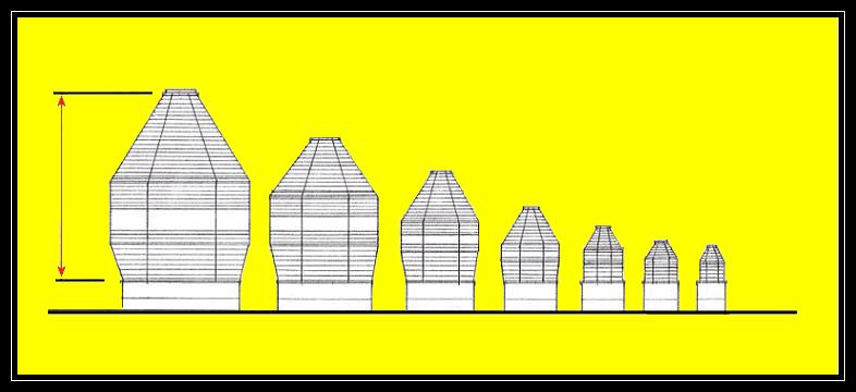
While the table shown above gives information on the seven (7) primary Orders of Fresnel Lenses, there were actually a total of eleven (11) Orders that were manufactured in all. There were two super size lenses called a Hyper-Radial and a Meso-Radial lens, both of which were larger than the First Order, and a Seventh and Eighth Order Lens, which of course, were consecutively smaller than the Sixth Order lens. Although there are references to the Meso-radial lens, none were actually built. Meso-radial lenses only existed on paper. If it was determined that there was a need for a more powerful light than a First order lens could produce, a Hyper-radial lens would be used.
One Hyper-Radial is in operation in the U.S., which leads to the following trivia question: Do you know where the largest Fresnel Lens is located in the U.S.? You can go to http://www.cr.nps.gov/maritime/light/makapuu.htm for the answer.
Different Styles of Fresnel Lenses
Not only were Fresnel lenses available in different sizes, but there were also a couple of different styles of the lenses. The most common and widely used style of lens is sometimes referred to as a “beehive” lens (for photos, see link below). In this style, a series of vertical panels were placed side by side and were attached to one another, forming a curtain or “beehive” shaped frame, which was set down around the light source. The frame could then be fitted with prisms to give off a fixed light, or give off a “flashing” signal when bull’s eyes were installed to concentrate the light and the frame was rotated at a constant speed.
Another type of Fresnel lens design is known as a “bi-valve” or “clamshell” lens (for photos, see link below). Although these lenses were used less frequently, they were just as effective and powerful lenses. This style of lens uses a two-sided frame that was set down around the light source like a partially opened clamshell. This lens style was fitted with bull’s eye prisms and then would be rotated at a certain speed to emit the desired characteristic. This style often used fewer prisms than the “beehive” style. It is interesting to note that a 2nd Order bi-valve would produce as much light as a 1st Order "beehive" lens with a smaller lamp. The only limitations with the bi-valve lens was the lack of different characteristics.
The final style of Fresnel lens used is known as the “drum” style. This lens style is the least common used and consisted of a cylindrical shaped frame that sat down around the light source. This frame was filled with prisms and generally gave off a constant or fixed characteristic. This style of lens was most often used in lightships.
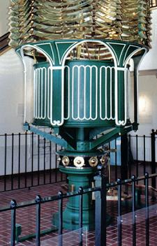
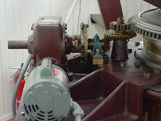
The "Clockwork" or Rotating Mechanism
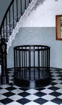
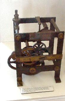
Lighthouse designers had to come up with a way to rotate the bull's-eye lenses to make use of its ingenious design. Giving the various weights and sizes of the lens, this was seemingly a difficult task, yet the answer was, in fact, quite simple. The lenses would be secured to a rotating stand, which was set atop a series of brass chariot wheels (see figure 1 below). A clockwork type mechanism (similar to that of a coo-coo clock) was located beneath the rotating stand and attached to the stand by a series of gears located along its base ( see figure 3 below). Weights were suspended down the center of the lighthouse by a series of cables that were looped through small rings (see figure 4 below) that were fashioned into each landing of the stairway. These cables were also wrapped around a drum attached to the clockwork mechanism. As gravity pulled the weights toward the ground floor of the lighthouse, the drum was turned by the cable, which in turn, turned the gears attached to the rotating stand. As the rotating stand turned, so did the lens. In order to keep the lens rotating, the light keeper had to periodically crank the weight back up to the top of the lighthouse. A small pit or "weight catcher" (see figure 2 below) was installed in a number of lighthouses as a safe area for the weight to decend into. As electricity became available in the lightstations, electric motors (see figure 5 below) replaced the traditional weight-driven system. The electric motors provided a more reliable and consistent way to rotate the lenses.
In the early days of lighthouse design, lantern rooms were equipped with simple tools used to emit and broadcast light. By the early 1800’s, a simple lamp or lantern would be fueled by an illuminant such as whale oil to produce a light. The light would then be focused by a silver mirror-like parabolic reflector around the light source, sending a beam of light out to mariners as they passed. This method was widely used, but as was often the case, was ineffective at marking the hazards for mariners. It wasn't until 1822 when the young French physicist Augustin Jean Fresnel developed a curtain of glass prisms and lenses, which is known today as the Fresnel lens.
Fresnel's newly designed lens became an overnight success in Europe. However, it wasn't’ until 1841 that the Fresnel lens was first used in America, and only then in a very few select lighthouses. The first installation was in Navesink, New Jersey.
The delay of the installation of theses lenses in US lighthouses was due in part to 5th Auditor General, Stephen Pleasonton's unwillingness to justify the cost of the new lenses. When first told about the newly designed lens he actually dismissed its importance by thinking it was nothing more than a "fad" of the time. This was but one of Pleasonton's austere decisions which would later come back to haunt the Lighthouse Board. The cost of a 1st Order lens in 1851 was approximately $6,800 each, 2nd Order lenses were $4,400each, and 3rd Order lenses were $1860 each. The smaller Orders were proportionally less. (Note: In today's market a 1st Order lens is worth over $2,000,000, however, there are none to be sold.)
When the Lighthouse Board was established pursuant to an Act of Congress dated 3 March 1851 on the 21st of May 1851 the "new" lenses began replacing the old reflectors at a rapid rate. Within a few short years most U.S. lighthouses were retrofitted with the Fresnel.
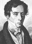
Biography of Augustin Fresnel
Augustin Fresnel (pronounced fru-NELL) was born on May 10, 1788 to Jacques and Augustine Fresnel. His parents provided the majority of his early childhood schooling, but at the age of twelve, he was enrolled in a school in Caen. He quickly began to show an interest in science and math and later earned a degree in civil engineering. Augustin worked in his spare time on experiments with light, a subject with which he was fascinated. In 1815, he published his first report on the wave theory of light and attempted to explain the phenomenon known as diffraction.
After being commissioned by the French government in 1819, Fresnel continued working on his various theories of light and optics. These theories and optical formulas included reflection, refraction, double refraction, and the polarization of light reflected from a transparent substance. In 1821 he felt confident enough to apply his theories into the development of his first trial lens.
In addition to being completely unique in its design, developmental tests showed that he could achieve approximately 80-85% total efficiency of light use. Prior to his design the best that could be achieved was only 17%, using reflectors.
Augustin continued his experiments with light waves and diffraction. In 1822 Fresnel's prototype was completed and installed at France's Gironde River light. On-site testing showed that this new lens could project a concentrated light beam 20 miles out to sea, an amazing accomplishment for its time. Not only was the light very powerful, but it also was considered quite energy efficient, as well. By utilizing prisms and horizontal bands in the glass coupled with a smaller light source, the amount of fuel needed was reduced significantly.
Due to Fresnel's diligent effort in studying ways to manipulate light through lens development, he was appointed to the lighthouse commission in 1824 where he continued to develop the use of lenses in lighthouses. After struggling throughout his life with ill health, Fresnel died in 1827 at the early age of 39.
Order
of Lens
First
Second
Third
Third & 12
Fourth
Fifth
Sixth
Typical
Usage
Largest of Seacoast Lights
Great Lakes & Seacoast Lights
Seacoast, Great Lakes, Bays & River Entrance Lights
Mainly Designed for use on the Great Lakes
Reefs, Harbor and Shoal Lights
Breakwaters, Channel Markers, and Lights Marking Small Islands
Pier and Breakwater lights
Overall
Height
7' 10"
6'1"
4' 8"
3' 0"
2' 4"
1' 8"
1' 5"
Interior
Diamater
6' 7/16"
4' 7"
3' 3"
2' 6"
1' 8"
1' 3"
1' 0"
Weight (including
metal frame)
6,000 lbs
3530 lbs
1985 lbs
1000-1200 lbs.
440 - 660 lbs
265 - 440 lbs
220 lbs
Approximate
Distance Seen
22 miles
20 miles
18 miles
17 miles
15 miles
10 miles
5 miles
Figure 1
Note the brass chariot wheels, gears above the wheels, and that the lens is supported by the rotating section of the stand.
This gear mechanism is on display at the Bodie Island lighthouse. The item on the top-left of the mechanism connected to the gears on the rotating stand. The large bottom gear was turned by the cable as the weight lowered through the tower.
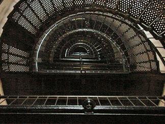
In the center of this photo of the staircase in the Bodie Island lighthouse are the rigs that were fashioned to each of the landings of the staircase for use with a bull's-eye lens. As luck would have it, the lighthouse was filled with a fixed first-order lens. The clockwork and weight system was never used at this station even though it was constructed with the capability.
Figure 4
Figure 5
This is the current electric motor which turns the lens in the Jupiter Inlet lighthouse in Florida.
The following companies in and around the Paris, France area produced most of the Fresnel Lenses that would end up being purchased and used in the United States:
Letourneau & Company
Henry - Lepaute
Lemonier
Barbier, Fenestre & Turenne
In addition, the following companies were used to manufacturer Fresnel Lenses outside of France.
Chance Brothers (England)
Wilhelm Wieule (Germany)
Macbeth-Evans (United States)
Orders
Through continued research and development, it was learned that smaller lenses could be used in many locations other than on the coastal areas. Locations such as harbors, bays, rivers, inlets and even some coastal areas were considered for these smaller lenses. Fresnel began his work on the development of various sizes (to be called "Orders") to suit the needs of different locations. The higher the "Order" number, the smaller the lens. Below, you will find a chart showing the 7 primary "Orders" which he developed. Please note that the "typical Usage" listed in the table below is a general guide. The order of the lens to be used in a specific lighthouse would be determined by the specific needs at each individual location.
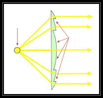
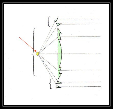
Light from a general source (candle, lamp, or lantern) would be emitted and collected by the dioptric set of prisms assembled in the center portion of the lens. The dioptric prisms would then refract the light, increasing the distance the light could be seen (see Drawing 2).
The catadioptric prisms, the upper and lower prism groups (see Drawing 3) collect the light as well, then refract and reflect the light so that all the light coming through the prisms in the vertical panel is a unified, far reaching beam.
It is important to note here that there is NO magnifiaction in the operation of a Fresnel lens. Magnification is the act of increasing the available light, yet the Fresnel lens only redirects what light is available.
Drawing 2
Drawing 3
Drawing 1
Initially, there were few choices of characteristics available. The first choice of characteristic was a fixed lens that gave of a constant light. The next choice of characteristic was a “flashing” lens with 8, 12,16, or 24 flash panels. The final choice of characteristic was fixed lens, which would be varied, by the placement of flash panels to interrupt the fixed signal. These were varied in their placement along the coast so that the pattern would not be duplicated too often to prevent confusing the mariner as to his location.